

Rotec China Office nimmt offiziell den Betrieb auf
Click to view Rotec China Office nimmt offiziell den Betrieb auf
Rotec Munich setzt seinen internationalen Wachstumskurs konsequent fort: Das neue ROTEC China Office hat...

Torsional vibration is one of the most damaging — and most overlooked — dynamic phenomena in rotating machinery.
It doesn't announce itself with a loud bang.
Instead, it works quietly inside crankshafts, turbine shafts, and gearboxes until fatigue cracks, gear damage, or catastrophic failure bring an otherwise "healthy" machine to a stop.
This guide explains what torsional vibration is, why it matters across industries, and how it is measured and analysed —
with a look at the tools and methods engineers use to keep rotating systems reliable.

Torsional vibration is the oscillation of angular velocity in a rotating shaft, caused by fluctuating torque. Rather than moving smoothly at a constant rotational speed, the shaft speeds up and slows down slightly within every revolution — even though the average RPM stays the same.
It occurs in virtually any machine with rotating components: combustion engines, steam and gas turbines, electric motors, generators, and gearboxes. A textbook example is the automotive crankshaft, which experiences non-uniform rotational speed during operation as each combustion event delivers a torque pulse, even though the engine's average RPM appears perfectly steady on the dashboard.
Left unmanaged, these speed fluctuations create cyclical stress that leads to component fatigue, cracking, and — in severe cases — catastrophic failure. That's why monitoring and mitigating torsional vibration is a core discipline in machine design, testing, and condition monitoring.
Torsional vibration matters in a wide range of rotating systems:
Internal combustion engines. Combustion events cause the crankshaft to speed up and slow down within each cycle, creating cyclical stress that accelerates wear on couplings, bearings, and gears. Torsional vibration isn't only generated by compression and combustion — load impacts throughout the drivetrain contribute too. Understanding this link between engine orders and NVH (noise, vibration, harshness) behaviour lets engineers spot weak points, improve durability, and refine ride comfort.
Steam and gas turbines. Here, torsional vibration arises from the interaction between rotating shafts and fluctuating steam or gas flow. In power generation, external factors such as grid feedback or sub-harmonics add further complexity, and unmanaged vibration can damage shafts, rotors, and bearings — leading to costly downtime.
Electric vehicles. EV drivetrains experience high-frequency torsional oscillations driven by rapid motor acceleration and deceleration. Beyond the immediate NVH impact on passenger comfort, sustained torsional vibration accelerates wear on transmission gears and motor bearings, shortening service life.
Wind turbine gearsets. Planetary gearsets transfer highly variable rotational energy from the blades to the generator. Fluctuating wind speed translates directly into torsional vibration, which can cause misalignment, gear tooth wear, and fatigue failure if not properly managed.
Across all of these applications, unmanaged torsional vibration shows up as gear whine, clutch chatter, synchronisation problems, or reduced precision — all of which raise maintenance costs and shorten component life.
Measuring torsional vibration means accurately capturing tiny variations in rotational speed, typically using sensors that deliver multiple samples per shaft revolution. Common sensor types include:
Magnetic pickups — robust, low-cost, and easy to install, though limited by the number of gear teeth available for measurement
Optical encoders — using zebra tape or zebra discs for higher pulse rates and finer precision, though sensitive to dirt, dust, and oil
Incremental encoders — high-resolution devices that deliver enough data per revolution to analyse high-order effects, useful for transmission error analysis and gear meshing order identification
Rather than relying on time-based data as is typical in classic NVH work, an angle-based measurement approach — using high-resolution counters operating in the gigahertz range — delivers highly accurate results and fast FFT processing thanks to smaller data files. The captured angle-domain data is then processed with dedicated software to identify frequency and amplitude changes across the full RPM range.
Want the technical detail? Read our in-depth guide to torsional vibration measurement.
Torsional orders are multiples of the fundamental rotational speed, and they're the key to tracing vibration back to its source. In engine analysis, the torsional order corresponds to the number of significant torque pulses per revolution — in an evenly firing four-cylinder four-stroke engine, for instance, the second order typically lines up with the firing events.
Because real torque pulses aren't purely sinusoidal, harmonics appear in the spectrum alongside the fundamental order. Correctly interpreting these orders — and the harmonics they generate — is essential for diagnosing multi-cylinder engines and other rotating systems accurately.
Engineers commonly visualise torsional orders using:
Waterfall diagrams — showing amplitude across orders and speed in a 3D view
Contour diagrams — a top-down heat-map view of the same data
Campbell diagrams — plotting order lines against frequency and speed to spot resonance crossings
See how this works in practice on our torsional vibration analysis page.
Torsional resonance occurs when a system's natural frequency coincides with an external driving frequency, amplifying oscillations. In engines, for example, crankshaft resonance at a specific RPM can cause the shaft to twist excessively, amplifying vibration throughout the whole system. Identifying and avoiding resonance conditions through careful design and tuning is critical for the longevity of any rotating machine.
Several complementary strategies help keep torsional vibration under control:
Tuning engine or transmission parameters to reduce irregular torque pulses
Isolation using dampers, flexible couplings, or rubber mounts to absorb vibration before it spreads
Design matching to shift natural frequencies away from operating speeds and avoid resonance
Active vibration control, where sensors and actuators counteract vibration in real time
Choosing the right sensor and test setup depends on your application, precision requirements, and environment. Our dedicated pages cover this in detail:
Torsional vibration sensors — sensor types, comparison, and how to choose the right one
Torsional vibration testing — how test systems are set up for engines, turbines, and drivetrains
Torsional vibration measurement is a vital part of designing, testing, and maintaining rotating machinery. By understanding its causes and applying accurate measurement and order analysis, engineers can catch problems early, extend component life, and improve overall system performance — whether the application is an automotive engine, an industrial turbine, or an electric drivetrain.
An oscillating rotational movement superimposed on the mean rotation. Fluctuating torque causes the shaft to accelerate and decelerate within a revolution.
An order expresses a vibration frequency as a multiple of rotational frequency. Order analysis helps investigate speed-related excitation and potential resonances.
Vibration amplitudes can increase when an excitation frequency approaches a natural frequency. The response depends on factors including damping and system configuration.
Discuss your measurement task, operating conditions and suitable analysis with ROTEC.
Discuss your project →ROTEC KNOWLEDGE
Torsional vibration is one of the most damaging — and most overlooked — dynamic phenomena in rotating machinery.
It doesn't announce itself with a loud bang.
Instead, it works quietly inside crankshafts, turbine shafts, and gearboxes until fatigue cracks, gear damage, or catastrophic failure bring an otherwise "healthy" machine to a stop.
This guide explains what torsional vibration is, why it matters across industries, and how it is measured and analysed —
with a look at the tools and methods engineers use to keep rotating systems reliable.
Torsional vibration is the oscillation of angular velocity in a rotating shaft, caused by fluctuating torque. Rather than moving smoothly at a constant rotational speed, the shaft speeds up and slows down slightly within every revolution — even though the average RPM stays the same.
It occurs in virtually any machine with rotating components: combustion engines, steam and gas turbines, electric motors, generators, and gearboxes. A textbook example is the automotive crankshaft, which experiences non-uniform rotational speed during operation as each combustion event delivers a torque pulse, even though the engine's average RPM appears perfectly steady on the dashboard.
Left unmanaged, these speed fluctuations create cyclical stress that leads to component fatigue, cracking, and — in severe cases — catastrophic failure. That's why monitoring and mitigating torsional vibration is a core discipline in machine design, testing, and condition monitoring.
Torsional vibration matters in a wide range of rotating systems:
Internal combustion engines. Combustion events cause the crankshaft to speed up and slow down within each cycle, creating cyclical stress that accelerates wear on couplings, bearings, and gears. Torsional vibration isn't only generated by compression and combustion — load impacts throughout the drivetrain contribute too. Understanding this link between engine orders and NVH (noise, vibration, harshness) behaviour lets engineers spot weak points, improve durability, and refine ride comfort.
Steam and gas turbines. Here, torsional vibration arises from the interaction between rotating shafts and fluctuating steam or gas flow. In power generation, external factors such as grid feedback or sub-harmonics add further complexity, and unmanaged vibration can damage shafts, rotors, and bearings — leading to costly downtime.
Electric vehicles. EV drivetrains experience high-frequency torsional oscillations driven by rapid motor acceleration and deceleration. Beyond the immediate NVH impact on passenger comfort, sustained torsional vibration accelerates wear on transmission gears and motor bearings, shortening service life.
Wind turbine gearsets. Planetary gearsets transfer highly variable rotational energy from the blades to the generator. Fluctuating wind speed translates directly into torsional vibration, which can cause misalignment, gear tooth wear, and fatigue failure if not properly managed.
Across all of these applications, unmanaged torsional vibration shows up as gear whine, clutch chatter, synchronisation problems, or reduced precision — all of which raise maintenance costs and shorten component life.
Measuring torsional vibration means accurately capturing tiny variations in rotational speed, typically using sensors that deliver multiple samples per shaft revolution. Common sensor types include:
Magnetic pickups — robust, low-cost, and easy to install, though limited by the number of gear teeth available for measurement
Optical encoders — using zebra tape or zebra discs for higher pulse rates and finer precision, though sensitive to dirt, dust, and oil
Incremental encoders — high-resolution devices that deliver enough data per revolution to analyse high-order effects, useful for transmission error analysis and gear meshing order identification
Rather than relying on time-based data as is typical in classic NVH work, an angle-based measurement approach — using high-resolution counters operating in the gigahertz range — delivers highly accurate results and fast FFT processing thanks to smaller data files. The captured angle-domain data is then processed with dedicated software to identify frequency and amplitude changes across the full RPM range.
Want the technical detail? Read our in-depth guide to torsional vibration measurement.
Torsional orders are multiples of the fundamental rotational speed, and they're the key to tracing vibration back to its source. In engine analysis, the torsional order corresponds to the number of significant torque pulses per revolution — in an evenly firing four-cylinder four-stroke engine, for instance, the second order typically lines up with the firing events.
Because real torque pulses aren't purely sinusoidal, harmonics appear in the spectrum alongside the fundamental order. Correctly interpreting these orders — and the harmonics they generate — is essential for diagnosing multi-cylinder engines and other rotating systems accurately.
Engineers commonly visualise torsional orders using:
Waterfall diagrams — showing amplitude across orders and speed in a 3D view
Contour diagrams — a top-down heat-map view of the same data
Campbell diagrams — plotting order lines against frequency and speed to spot resonance crossings
See how this works in practice on our torsional vibration analysis page.
Torsional resonance occurs when a system's natural frequency coincides with an external driving frequency, amplifying oscillations. In engines, for example, crankshaft resonance at a specific RPM can cause the shaft to twist excessively, amplifying vibration throughout the whole system. Identifying and avoiding resonance conditions through careful design and tuning is critical for the longevity of any rotating machine.
Several complementary strategies help keep torsional vibration under control:
Tuning engine or transmission parameters to reduce irregular torque pulses
Isolation using dampers, flexible couplings, or rubber mounts to absorb vibration before it spreads
Design matching to shift natural frequencies away from operating speeds and avoid resonance
Active vibration control, where sensors and actuators counteract vibration in real time
Choosing the right sensor and test setup depends on your application, precision requirements, and environment. Our dedicated pages cover this in detail:
Torsional vibration sensors — sensor types, comparison, and how to choose the right one
Torsional vibration testing — how test systems are set up for engines, turbines, and drivetrains
Torsional vibration measurement is a vital part of designing, testing, and maintaining rotating machinery. By understanding its causes and applying accurate measurement and order analysis, engineers can catch problems early, extend component life, and improve overall system performance — whether the application is an automotive engine, an industrial turbine, or an electric drivetrain.
An oscillating rotational movement superimposed on the mean rotation. Fluctuating torque causes the shaft to accelerate and decelerate within a revolution.
An order expresses a vibration frequency as a multiple of rotational frequency. Order analysis helps investigate speed-related excitation and potential resonances.
Vibration amplitudes can increase when an excitation frequency approaches a natural frequency. The response depends on factors including damping and system configuration.
Discuss your measurement task, operating conditions and suitable analysis with ROTEC.
Discuss your project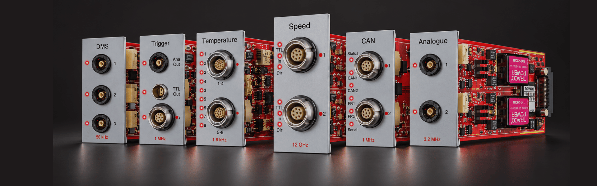






Präzise Ergebnisse entstehen durch das Zusammenspiel von Sensorik, Signalaufbereitung, Datenerfassung, Analyse und technischem Systemverständnis.
Steuertrieb, Nebenaggregate, Kupplung und Dämpfer, Getriebe sowie Ventildynamik werden gezielt analysiert, um das dynamische Verhalten des Verbrennungsmotors ganzheitlich zu verstehen.

Präzise Ergebnisse entstehen durch das Zusammenspiel von Sensorik, Signalaufbereitung, Datenerfassung, Analyse und technischem Systemverständnis.