
Rotec China Office nimmt offiziell den Betrieb auf
Click to view Rotec China Office nimmt offiziell den Betrieb auf
Rotec Munich setzt seinen internationalen Wachstumskurs konsequent fort: Das neue ROTEC China Office hat...

Discuss your project →

A torsional vibration test captures how a shaft's rotational speed fluctuates across its full operating range — typically during a run-up test, where speed is swept from idle to maximum RPM while the measurement system records rotational speed variations continuously. Zooming into any short window of that run-up reveals the underlying oscillation: rapid speed fluctuations riding on top of the overall RPM trend, generated by torque pulses from combustion, gear meshing, or other rotating sources.
The goal of the test is to capture this behaviour with enough resolution and speed range coverage to identify:
Which torsional orders are present and how strong they areA torsional vibration test system typically combines:
A speed sensor (magnetic pickup, optical encoder, or incremental encoder) mounted on the shaft — crankshaft, camshaft, turbine shaft, or gearbox input/output shaft, depending on the application
Sensor electronics to condition and clean the raw signal
A high-resolution measurement device, using speed input boards operating in the gigahertz range to achieve very fine angular resolution regardless of sensor tooth count
Analysis software to process the angle-domain data into orders, spectra, and diagnostic diagrams
For applications with additional dynamic requirements — such as valvetrain behaviour on fired engines — the same measurement philosophy extends to fast analogue channels (multi-megahertz sampling) alongside the speed reference, enabling synchronised analysis of multiple fast-moving components in a single test.
A well-run test delivers more than a single number — it produces a set of diagnostic views engineers can act on directly:
Waterfall diagrams, showing how amplitude evolves across orders and speed
Contour diagrams, giving a fast visual overview of problem orders
Campbell diagrams, revealing where order lines cross natural frequencies — the classic signature of a resonance risk
Quantified seating, lift-off, or dynamic behaviour data for valvetrain-specific tests
These results feed directly into design decisions: adding or tuning dampers, revising gear or valvetrain geometry, or comparing the results with agreed technical assessment criteria.
ROTEC's single-source approach covers the entire measurement chain — sensors, signal conditioning, high-resolution data acquisition, and post-processing analysis software — backed by decades of engineering experience across racing, road, and heavy-duty applications. That combination is what turns raw speed data into a reliable diagnosis, not just a chart.
Speed fluctuations and vibration amplitudes across the agreed speed and load range. The assessment can examine orders, indications of resonance and differences between operating points.
Depending on the test brief, outputs include order, waterfall, contour or Campbell diagrams and a technical assessment. Measurement scope and assessment criteria are agreed for the application.
ROTEC ENGINEERING supports measurement-point design and sensor installation through to measurement, analysis and presentation of the results.
Discuss your measurement task, operating conditions and suitable analysis with ROTEC.
Discuss your project →ROTEC KNOWLEDGE
A torsional vibration test captures how a shaft's rotational speed fluctuates across its full operating range — typically during a run-up test, where speed is swept from idle to maximum RPM while the measurement system records rotational speed variations continuously. Zooming into any short window of that run-up reveals the underlying oscillation: rapid speed fluctuations riding on top of the overall RPM trend, generated by torque pulses from combustion, gear meshing, or other rotating sources.
The goal of the test is to capture this behaviour with enough resolution and speed range coverage to identify:
Which torsional orders are present and how strong they areA torsional vibration test system typically combines:
A speed sensor (magnetic pickup, optical encoder, or incremental encoder) mounted on the shaft — crankshaft, camshaft, turbine shaft, or gearbox input/output shaft, depending on the application
Sensor electronics to condition and clean the raw signal
A high-resolution measurement device, using speed input boards operating in the gigahertz range to achieve very fine angular resolution regardless of sensor tooth count
Analysis software to process the angle-domain data into orders, spectra, and diagnostic diagrams
For applications with additional dynamic requirements — such as valvetrain behaviour on fired engines — the same measurement philosophy extends to fast analogue channels (multi-megahertz sampling) alongside the speed reference, enabling synchronised analysis of multiple fast-moving components in a single test.
A well-run test delivers more than a single number — it produces a set of diagnostic views engineers can act on directly:
Waterfall diagrams, showing how amplitude evolves across orders and speed
Contour diagrams, giving a fast visual overview of problem orders
Campbell diagrams, revealing where order lines cross natural frequencies — the classic signature of a resonance risk
Quantified seating, lift-off, or dynamic behaviour data for valvetrain-specific tests
These results feed directly into design decisions: adding or tuning dampers, revising gear or valvetrain geometry, or comparing the results with agreed technical assessment criteria.
ROTEC's single-source approach covers the entire measurement chain — sensors, signal conditioning, high-resolution data acquisition, and post-processing analysis software — backed by decades of engineering experience across racing, road, and heavy-duty applications. That combination is what turns raw speed data into a reliable diagnosis, not just a chart.
Speed fluctuations and vibration amplitudes across the agreed speed and load range. The assessment can examine orders, indications of resonance and differences between operating points.
Depending on the test brief, outputs include order, waterfall, contour or Campbell diagrams and a technical assessment. Measurement scope and assessment criteria are agreed for the application.
ROTEC ENGINEERING supports measurement-point design and sensor installation through to measurement, analysis and presentation of the results.
Discuss your measurement task, operating conditions and suitable analysis with ROTEC.
Discuss your project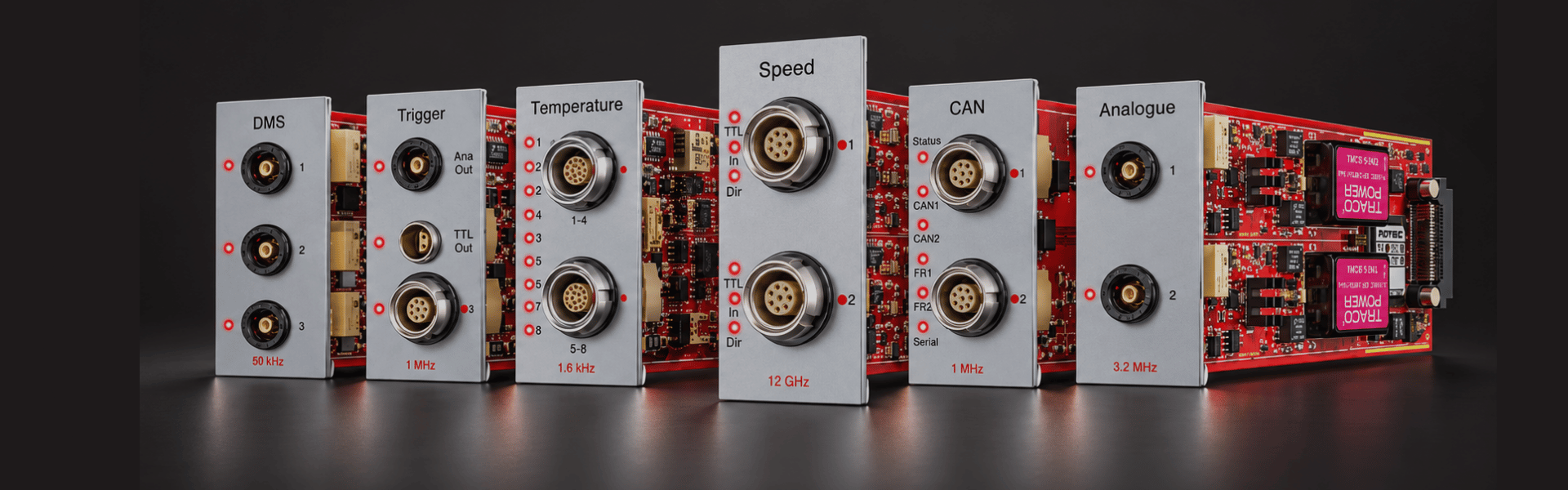





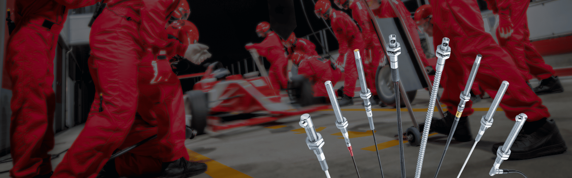
Präzise Ergebnisse entstehen durch das Zusammenspiel von Sensorik, Signalaufbereitung, Datenerfassung, Analyse und technischem Systemverständnis.
Steuertrieb, Nebenaggregate, Kupplung und Dämpfer, Getriebe sowie Ventildynamik werden gezielt analysiert, um das dynamische Verhalten des Verbrennungsmotors ganzheitlich zu verstehen.

Präzise Ergebnisse entstehen durch das Zusammenspiel von Sensorik, Signalaufbereitung, Datenerfassung, Analyse und technischem Systemverständnis.