-
Click to view Control driveControl drive
-
Click to view Auxiliary unitsAuxiliary units
-
Click to view Clutch/damperClutch/damper
-
Click to view TransmissionTransmission
-
Click to view NVH (Noise, Vibration, Harshness)NVH (Noise, Vibration, Harshness)
-
Click to view Valve dynamicsValve dynamics
Problem: Increased pollutant emissions, short service life of components
Goal: Precise design of the control drive
The focus of automobile development for internal combustion engines is on reducing fuel consumption and pollutant emissions. Timing drives and valve trains determine the efficiency of combustion processes. They are used to synchronize the crankshaft and camshaft to control the opening and closing behavior of the valves. A timing drive that is not optimally coordinated reduces the service life of the components and increases pollutant emissions.
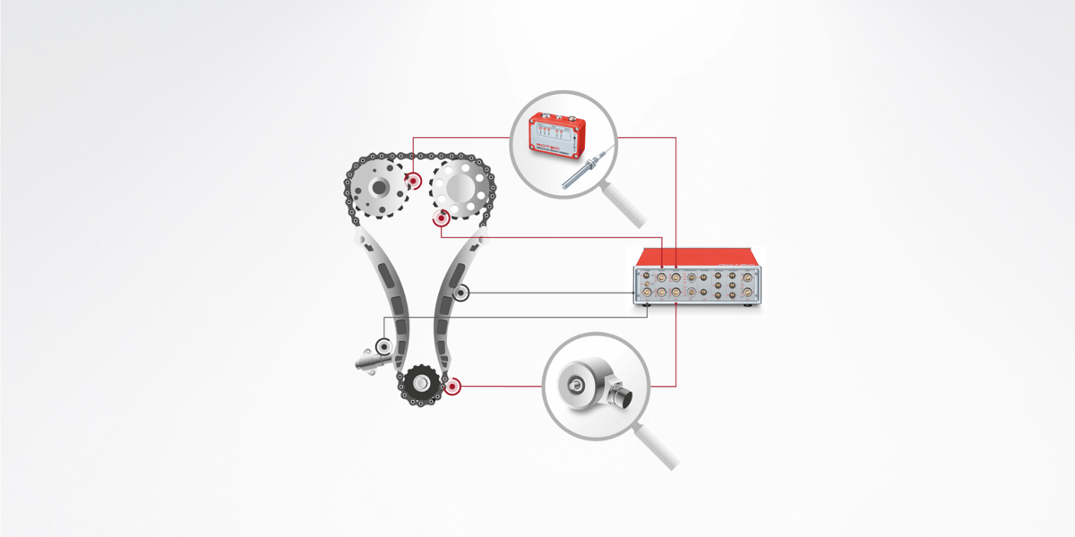
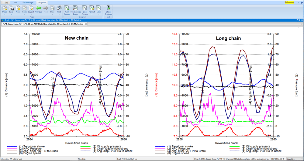
To examine the timing and valve trains, a multi-channel speed measurement is carried out on the camshafts and the position and speed on the crankshaft are measured using a rotary encoder. In combination with analog measured variables, the measurements provide a comprehensive overall picture of the dynamic behavior of the control drive under different load conditions. Analogue measured variables can be, for example, the oil pressure of the chain tensioner, the chain force and accelerations on the chain guides.
The recorded measured values are evaluated in the time and spectral domain.
ROTEC ENGINEERING also supports you with technical engineering knowledge on problems relating to vibration analyzes on engines, transmissions and drive trains. With our know-how, we make a valuable contribution to your product in the areas of timing train validation, valve train optimization, clutch design, transmission errors (TE), transmission and oil balance optimization, drive train measurement and optimization, current and voltage analysis as well as the application of measurement technology.
Analyzes in the time domain
- Tensioner forces
- Swing and twist angle analysis in phase
- Oil pressure conditions for hydraulic tensioners
- Closing behavior of the check valve
- Detection of loss of control
- Detecting chain or belt beating
- Detecting the startup noises
Analyzes in the spectral range
- Classic order and frequency analyses
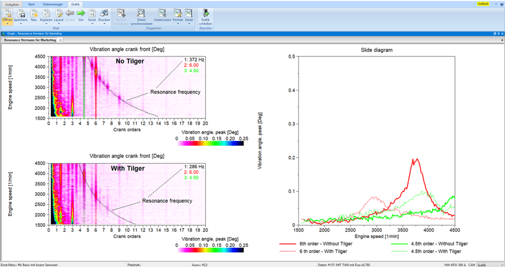
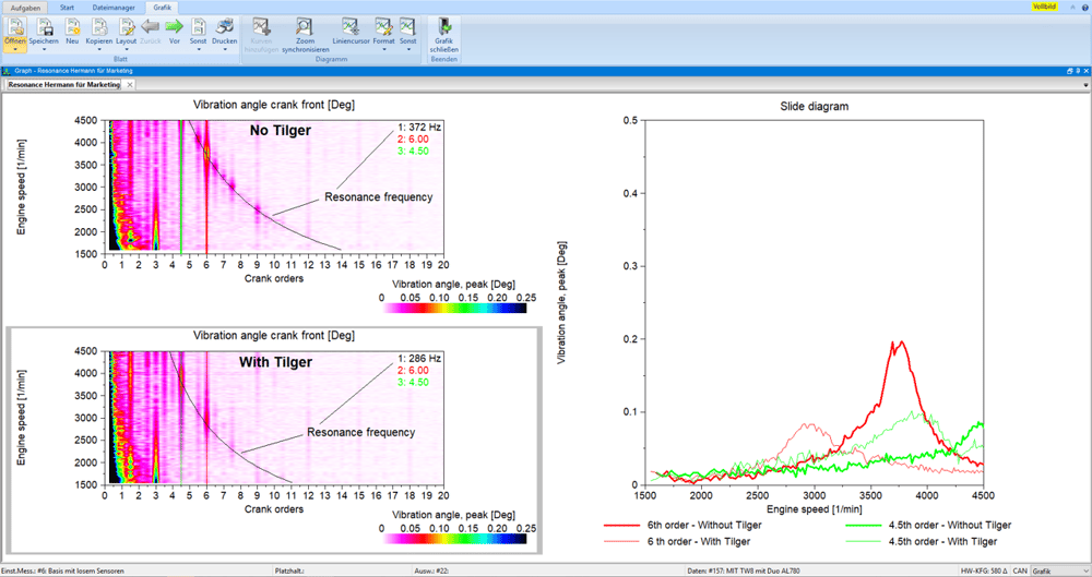
- Checking the resonance behavior of the drive
- Analysis of the suggestions
- Creation of envelope curves via speed
- Optimization of the phase position of the excitations (high-pressure pumps)
- Analysis of traction device noises
Problem: Slippage, belt vibration, wear of belt drive components
Goal: Precise design of the auxiliary units
Auxiliary drives such as the power steering pump or the air conditioning compressor, which regulates the temperature in the vehicle, ensure a high level of driving comfort. To avoid damage, you must always ensure the correct belt tension on the power take-offs. Too little tension leads to slippage and belt vibration, resulting in premature wear of the belt drive components.
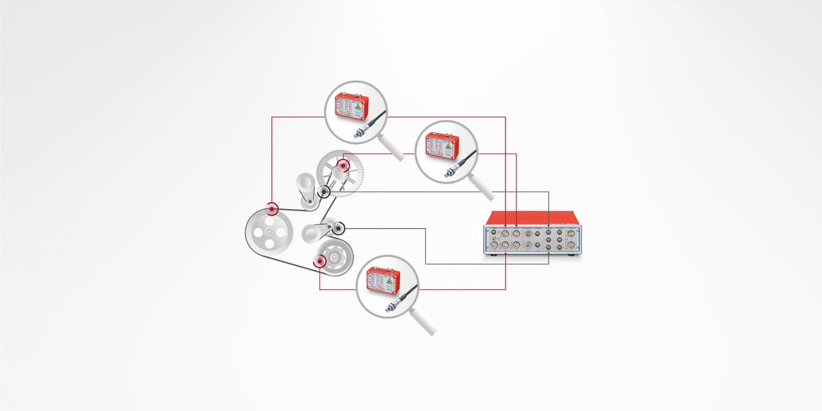
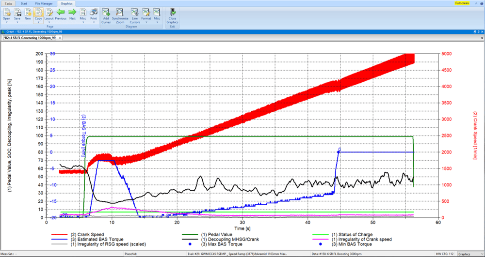
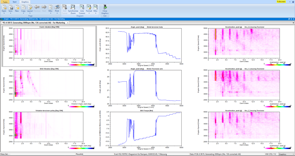
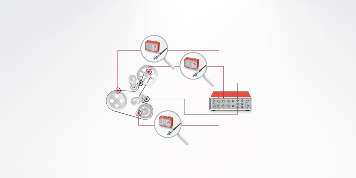
The functional tests on auxiliary drives (FEAD) and belt starter generator drives (BAS) include the measurement and evaluation of the slip and dynamic behavior of the entire belt drive system.
In addition to the high-resolution measurement of the rotation angle position of the crankshaft and all other pulleys, the belt forces, tensioner movements and belt vibrations are important measurement variables in the image. In addition, the operating state of the engine and the load conditions of the auxiliary units as well as the current torque of the BAS generator have a significant influence on the drive behavior. The evaluation takes place in the time and spectral domain.
The state of charge of the battery plays an important role in hybrid drives. Most sizes with sufficient resolution are available on the CAN BUS and can be recorded with the ROTEC CAN BUS card.
In BAS systems, the starting and stopping processes of the engine as well as the switching of the starter generator between engine and generator operation (recuperation) represent one of the most difficult dynamic conditions, which is why sensors with direction of rotation detection are required to record the correct speed ratios. ROTEC offers appropriate sensor solutions for this task, such as encoder adaptation modules or quadruple sensors.
The recorded measured values are evaluated in the time and spectral domain.
ROTEC ENGINEERING also supports you with technical engineering knowledge on problems relating to vibration analyzes on engines, transmissions and drive trains. With our know-how, we make a valuable contribution to your product in the areas of timing train validation, valve train optimization, clutch design, transmission errors (TE), transmission and oil balance optimization, drive train measurement and optimization, current and voltage analysis as well as the application of measurement technology.
Analyzes in the time domain
- Belt loads
- Bearing forces
- Tensioner preload and damping forces
- Force vector calculation depending on the clamp position
- Slipping behavior in the entire shoot
- Start and stop behavior
- Speed gradient and peak torque evaluations
Analyzes in the spectral range
- Resonance behavior of the tensioner
- Resonance behavior of the overall friction
- Automatic creation of result tables
- Decoupling behavior
Problem: crankshaft torsion, clutch slip
Goal: Optimal clutch design
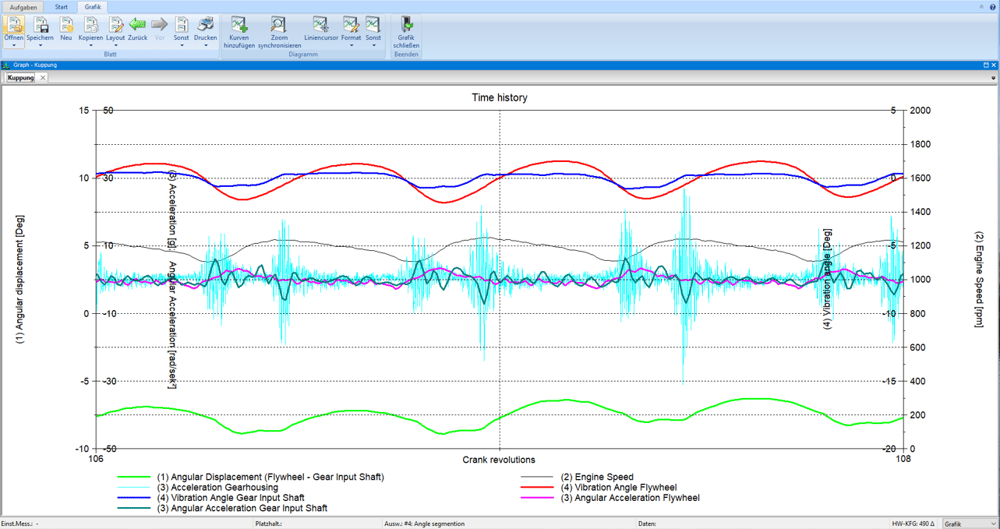
Modern engines are becoming increasingly compact, more powerful and more economical. This effect - also called downsizing - leads to an increase in combustion pressures and a reduction in the inertia of the crankshaft in internal combustion engines. Since this causes rotational irregularities to increase significantly, manufacturers of couplings and vibration dampers are faced with a new challenge. The measurement and evaluation of crankshaft torsion, clutch slip and the behavior of a vibration damper is therefore essential to ensure the functional reliability and service life of the individual components.
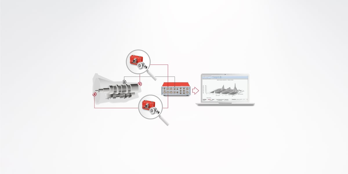
When measuring the clutch shown in the figure, the speed is measured using a magnetic sensor on the starter ring gear and on the transmission input shaft. The main evaluations are the twist angle between the engine (input) and gearbox side, slip, order analysis, especially angular accelerations in the gearbox (gearbox rattle).
In the ROTEC product portfolio you will find a variety of different speed sensors (laser and magnetoresistive) that are suitable for the respective installation situation, the environmental conditions and the optimal signal resolution. In order to be able to measure the twist angle between two speed signals with high resolution, ROTEC offers speed measurement cards with 12.3 GHz. At the same time, other analog signals can also be recorded (max. 24 bit and 3.2 MHz), so that a connection between torsional vibrations and, for example, noise can be analyzed. The recorded measured values are evaluated in the time and spectral domain.
The measured values recorded are evaluated in the time and spectral range.
ROTEC ENGINEERING also supports you with technical engineering knowledge on problems relating to vibration analyzes on engines, transmissions and drive trains. With our know-how, we make a valuable contribution to your product in the areas of timing train validation, valve train optimization, clutch design, transmission errors (TE), transmission and oil balance optimization, drive train measurement and optimization, current and voltage analysis as well as the application of measurement technology.
Analyzes in the time domain
- Analysis of static and dynamic deformations, angular accelerations (gear rattling) and the twist angle (clutch slap)
- Start and stop behavior
- Flywheel wobble
Analyzes in the spectral range
- Analysis of the dynamic stimuli
- Checking the decoupling behavior of the clutch
- Resonance behavior of the entire system
- Change in the natural frequencies of the ambient condition
- Dynamic peak loads
Problem: Gearbox noise, transmission error (TE, Transmission Error) Goal: Reliable design of the gearbox, noise reduction
Disturbing gearbox noises, vibrations and roughness (NVH, Noise Vibration Harshness) massively reduce driving comfort - especially in vehicles with low-noise electric motors. Noise can be reduced with a reliable gearbox design. This requires measuring and assessing the transmission error.
Gear noise
Gear whine is primarily caused by the tooth profile and tooth vibrations. In the spectrum of the transmission error and the structure-borne or airborne sound, the tooth meshing frequencies with their harmonics and modulation sidebands (caused by the rotational harmonics; e.g. concentricity errors) appear.
Gearbox whining can occur at high and low loads, gearbox rattling only at very low or no load (e.g. idling with a combustion engine). Then the fluctuation in speed originating from the engine (non-continuous combustion) causes the unloaded tooth flanks of the gears to lift off. The backlash is cycled with each acceleration and deceleration of the drive shaft (multiple times per revolution), causing the teeth of the two wheels to violently strike each other.
Other causes of gearbox noise can include incorrect gearbox oil or air pockets in the oil.
Transmission error (TE)
The main cause of gear noise is transmission errors (TE), which are caused by static and elastic deformation under load, unwanted manufacturing deviations and dynamic effects. The transmission error is the difference between the actual position of the driven gear and the position it would assume if the gear set transmitted the rotational movement of the drive gear with absolutely no errors.
In addition to gear noise, the transmission error can cause wear, reduced efficiency in the drive train or direct malfunctions (more about wind turbine gearboxes / rolling element gearboxes).
Measurements on gearboxes
To determine the transmission error, the speeds and angular positions are measured using high-resolution encoders on the input and output shafts. The transmission error is calculated from the measurement data obtained. The evaluation takes place in the time and order range.
At the same time, structure-borne noise signals are recorded with an accelerometer. The common time base of all measurement channels enables a correlation between transmission errors and sound signals.
ROTEC ENGINEERING
Do you need support with vibration analysis on engines, transmissions and drive trains? Our engineers will advise you with extensive specialist knowledge
- the validation of the control drive
- the optimization of the valve train
- the design of the coupling in the event of transmission errors
- when optimizing transmission and oil balance the measurement and optimization of the drive train current and voltage analysis as well the application of measurement technology.
Analyzes in the time domain
- Dynamic twist angle in transmission components
- Analysis of shaft torsion
- Sudden loads during load changes
- Analysis of the stiffness in the drive
Analyzes in the spectral range
- Analysis of the dynamic suggestions
- Checking the vibration dampers and coupling systems
- Resonance behavior of the entire system
- Change in natural frequencies over ambient conditions
- Dynamic peak loads
Analysis of acoustic behavior
- Identification of noise sources
- Detection of component resonances
- Specialized software solution for transmission testing
Problem: Audible and noticeable vibrations
Goal: increasing driving comfort
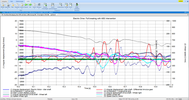
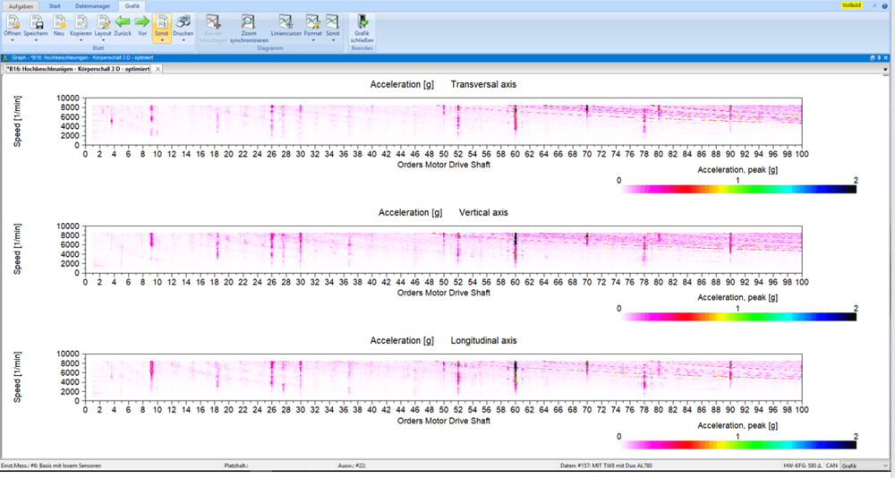
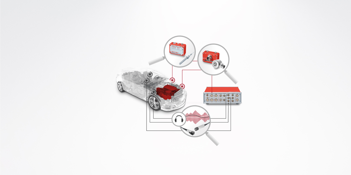
The noise and vibration behavior (NVH = Noise, Vibration, Harshness) of vehicles is increasingly becoming the focus of automotive development with regard to driving comfort. This refers to all the audible and noticeable vibrations that come from the chassis, drive train and wheels and influence comfort. Battery-operated electric drives represent a particularly big challenge here, as no combustion engine covers the drive noise and these can be perceived more as structure-borne or airborne noise. Several effects can be cited as the cause of the drive noise. Excitements on the drive side can occur that are caused by the electric motor, the gearbox or the drive shafts. Certain component groups can react to these structure-borne sound excitations with natural vibrations and further worsen the NVH behavior.
To measure and evaluate the vibrations, the speeds of the components that stimulate torsional vibrations are recorded. At the same time, structure-borne sound signals are recorded with an accelerometer and microphones and then evaluated together in the order and frequency ranges. For NVH examinations, ROTEC offers high-resolution analog measurement cards with ICP inputs and special NVH features in the analysis software.
The measured values recorded are evaluated in the time and spectral range. At the same time, the acoustic behavior is analyzed.
ROTEC ENGINEERING also supports you with technical engineering knowledge on problems relating to vibration analyzes on engines, transmissions and drive trains. With our know-how, we make a valuable contribution to your product in the areas of timing train validation, valve train optimization, clutch design, transmission errors (TE), transmission and oil balance optimization, drive train measurement and optimization, current and voltage analysis as well as the application of measurement technology.
Analyzes in the time domain
- Analysis of the curves of structure-borne noise signals in the time domain
- Correlation between dynamic component movements and noise effects
- Research into the causes of gear rattles or similar problems

Analyzes in the spectral range
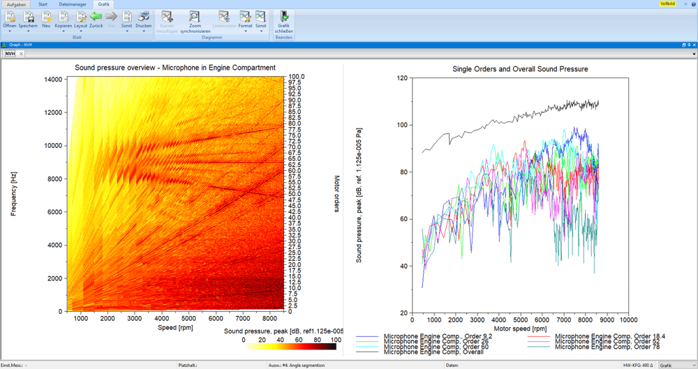
- Visualization of the composition of a soundscape
- Analysis of the individual orders and the overall noise level
- Analysis of the conspicuousness and dominance of a noise component
- Detecting resonances
- Comparison of the noise pattern at different locations
- Checking the effectiveness of sound insulation
Problem: Increased pollutant emissions
Goal: Efficient and powerful combustion engine
The development of efficient and powerful internal combustion engines is one of the main goals of automobile development. In this context, valve control is a crucial element for optimizing thermodynamics and therefore the efficiency of internal combustion engines.
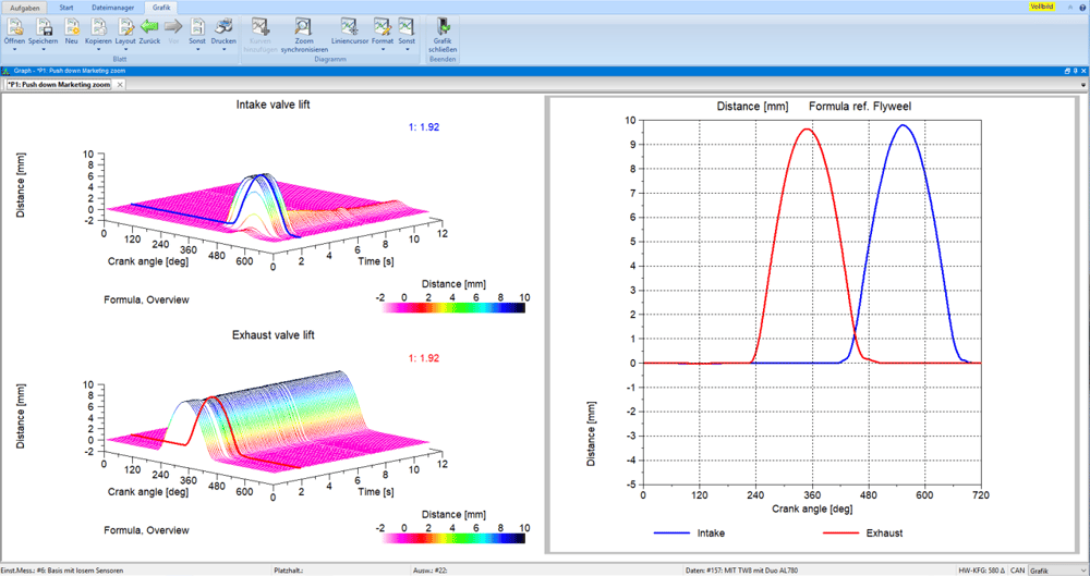
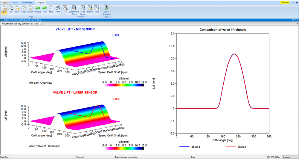
The analysis of the valve control is based on the measured, analog variables of valve lift or valve speed depending on the camshaft position. The focus is particularly on the dynamic opening and closing behavior of the valve (e.g. closing speed) depending on the engine speed.
Measurements on the dragged cylinder head and on the fired engine
In order to reliably assess the opening and closing behavior, measurements and calculations of the three measured variables valve lift, valve speed and valve acceleration are necessary. Two different measuring methods can be used for this: the measurement on the motorized cylinder head with a laser vibrometer and in the fired operation with magnetoresistive (MR) sensor technology from Sensitec. The measured variable valve lift can be determined both on the motorized cylinder head and in fired operation using MR sensors. For this purpose, the speed signals and angular positions on the camshaft drive system are recorded. In a first step, the torsional vibration behavior of the camshafts can be derived from this. The measured speed and valve lift data can then be evaluated in the valve train software module. This means that variables such as valve speed and acceleration, opening and closing behavior, stroke loss, resonance and voltage behavior can be automatically evaluated and displayed graphically.
Advantages of valve train investigations on a fired engine
The measurements on the fired engine have advantages over those on the dragged cylinder head. For example, you can also examine the effects of the gas forces under real torsional vibration and thermal expansion behavior of the camshafts or the cylinder head on a fired engine. These effects become more and more important as the charging and exhaust backpressures (particulate filters) increase.
Another advantage is that the costs for the construction of a sometimes very complex test sub-carrier can be saved.
Software module for automated evaluation of dynamic parameters
The manual evaluation of dynamic parameters, such as the valve opening speed or the time of dynamic opening and closing, is very laborious given a large number of different operating points and takes up a lot of your working time.
The “Valve Drive” software module was developed with the aim of carrying out these evaluations automatically. This means that not only the evaluation time, but also the size of the test matrix and, accordingly, the usage time of the test bench can be reduced. Instead of taking measurements at constant, discrete speeds, you can now perform speed ramps.
Among other things, the following parameters can be evaluated with the software module: angular position of dynamic opening and closing, contact speed, stroke loss, lifting, valve bounce, mechanical load on the components (surface pressure on the cup drive), stroke area and valve overlap.
The software evaluates the curves of several signals (stroke, speed and acceleration) and automatically displays them in a comparable manner for each cycle with the corresponding result parameters. For some analyses, additional evaluation methods are stored for the specialized user (e.g. touchdown speed).
In addition to the variety of analysis options, you can automatically record cycles with signal errors and remove them from the evaluations.
The application of the measurement technology as well as on-site measurements, analysis and evaluation can be completely provided and carried out by ROTEC ENGINEERING.
ROTEC ENGINEERING carries out tests on both electrical and hydraulic camshaft adjusters. This means that interactions between valve actuation and control times are recorded or the functional behavior of the camshaft adjusters is explicitly analyzed.
- Measurement of valve lift and valve speed with laser vibrometer
- Camshaft position measurement with angle encoder
- Classic measuring method with high-precision measuring signals
Measurements on the fired engine
- Valve lift measurement with prepared valve stem and MR sensors
- Deviation from the laser vibrometer < 20 µm
- Special software solution for calculating the stroke signals from the sensor signals (SIN, COS)