.png?width=200&height=45&name=Design%20ohne%20Titel(50).png)

Problem: Higher Efficiency requirements / Cam wear
Goal: Variable, robust valve control with optimized valve timing
.png?width=2000&height=1414&name=Design%20ohne%20Titel%20(30).png)
Valve train analysis - optimization of valve actuation
High efficiency, reliability, and performance are key factors in the development of modern combustion engines.
A crucial factor in increasing the efficiency and wear resistance of internal combustion engines is the mechanical and thermodynamic optimization of valve actuation.
In order to reliably evaluate the opening and closing behavior, measurements and calculations of the three central variables are required:
Valve stroke
Valve velocity
Valve acceleration
Depending on the purpose of the measurement, two different measurement methods and procedures are used. The evaluation of the measurement data is independent of the measurement procedure and is performed using the same module in the Rotec software.
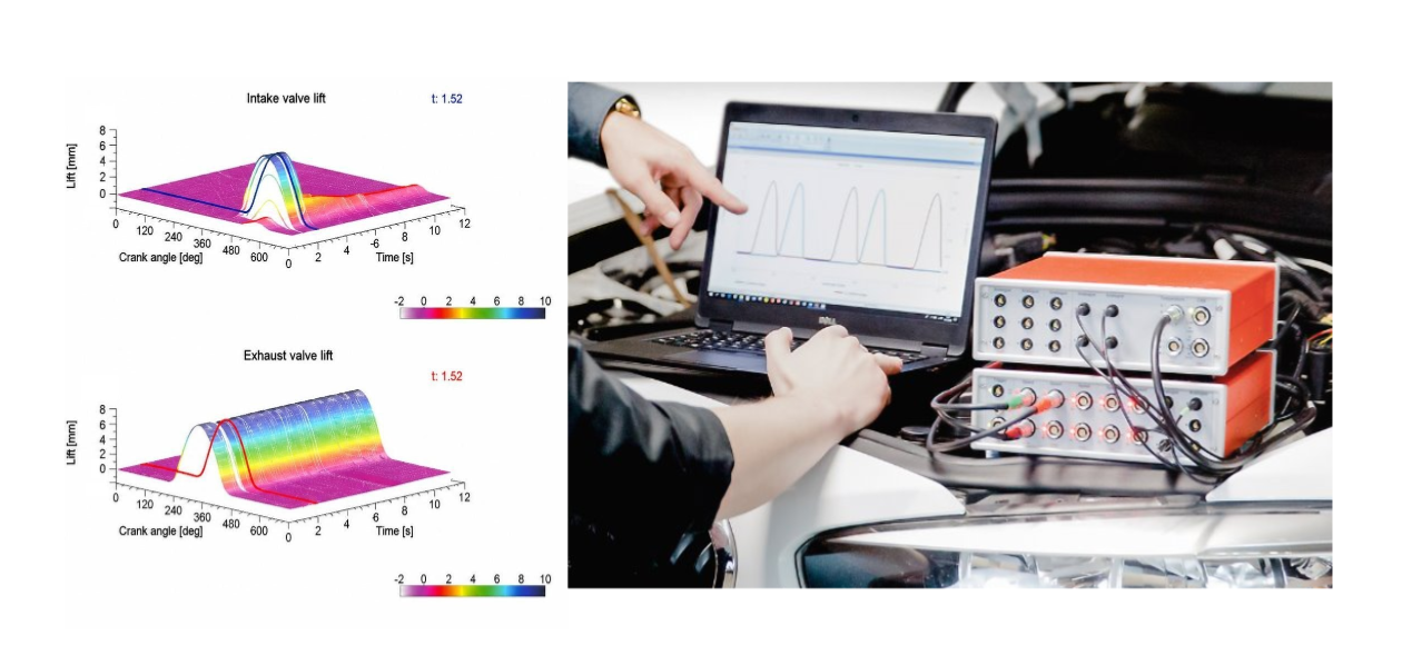
Measurement methods and procedures
Measurements on the motored cylinder head component
-Measurement of valve lift using simply installed optical sensors located outside the cylinder headMeasurements on the fired engine
.png?width=2000&height=1414&name=Design%20ohne%20Titel%20(29).png)
Analysis of valve actuation
The analysis of the valve train is based on analog measured signals of the valve lift sensor (SIN, COS). These signals are evaluated in relation to the crankshaft or camshaft position. The focus is particularly on the dynamic opening and closing behavior of the valve (e.g., closing speed) in relation to engine speed.
In addition, the RAS software offers a wide range of analysis tools. For example, it is possible to automatically evaluate valve closing behavior, valve overlap, lift loss, and lift-off. Other analog measured values such as spring and cam forces can also be integrated into the valve dynamics analysis.
Advantages of testing the valve train on a fired engine
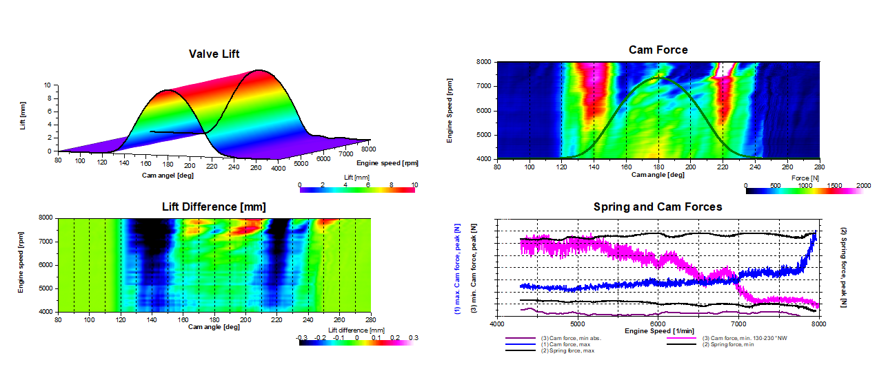
“Valve Train” software module - automated analysis
Manually evaluating dynamic parameters (e.g., valve closing velocity or the cam angles of dynamic opening and closing) is very time-consuming when dealing with variable valve actuation and many engine operating points and ties up valuable development resources. The “Valve Train” software module enables the automated evaluation of measurements at constant speeds as well as during speed ramps. This reduces the need for extensive measurement series that require long test bench capacity and speeds up the evaluation process. The software module can be used to evaluate and display many application-specific parameters:
Valve lift, velocity, and acceleration
Opening intervals or specific angular positions (e.g., for dynamic opening and closing)
Lift loss or lift comparison to the kinematic lift curve
Lift area and valve overlap
Lift-off and valve bounce
Closing velocity
Mechanical stress on components (e.g., surface stress in the tappet drive)
Analog values, such as parallel measured spring and cam forces
Min./max. values from valve lift, from derived curves and from parallel measured signals
The software evaluates the behavior of all opening and closing cycles recorded in the measurement. The results can be visualized by creating 2D and 3D graph plots based on rotational speed, angular position, and time. Individual cycles with signal errors can also be automatically detected and excluded from the analysis. Using the parallel recorded speed signals from the crankshaft or camshaft, it is also possible to determine the effects of torsional vibration behavior in the timing drive and valve train on the valve dynamics.